How to reset a polypropylene strapping machine manually?
How to reset a polypropylene strapping machine manually?
(2) Manual Feedback/Reset switch When the green light is lighted, press the button, you can feedback PP strap. When the yellow light is lighted, press the button, you can reset the machine. (3) Manual feed When in “reset” mode (green light is lighted), you can press the button to feed PP strap manually.
What are the components of a strapping machine?
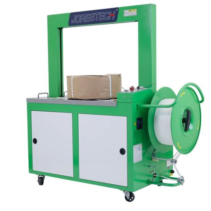
Major components 1 Introduction 1 Exterior Machine 2 Strapping Head 3 Installation 4 Operating Instructions 5 Operating Adjustments 7 Principles of Operation 8 Service Adjustments and Clearances 14 Maintenance 16 Troubleshooting 17 Parts list and Exploded views 18 Electrical schematic 35 MAJOR COMPONENTS
Where is the control panel on a strapping machine?
Control Panel. The control panel is located on the left-hand side of the front panel of the machine Refer to Figure 6. (1) Power Switch. Push on the button to make red light glow, which shows that all electrical circuits and the electric motor are energized. Then you can operate the machine Push down the button, power supply is cut off.
How to adjust the cooling time on a strapping machine?
The cooling time adjustment on your machine allows the user to adjust the cooling time to meet his strapping requirement. Please refer to page 34, turn the knob clockwise, the cooling time is longer. MOTOR STOP TIME DIP-SWITCH ADJUSTMENT The motor stop time adjustment on your machine allows the user to adjust the motor stop time.
(2) Manual Feedback/Reset switch When the green light is lighted, press the button, you can feedback PP strap. When the yellow light is lighted, press the button, you can reset the machine. (3) Manual feed When in “reset” mode (green light is lighted), you can press the button to feed PP strap manually.
Major components 1 Introduction 1 Exterior Machine 2 Strapping Head 3 Installation 4 Operating Instructions 5 Operating Adjustments 7 Principles of Operation 8 Service Adjustments and Clearances 14 Maintenance 16 Troubleshooting 17 Parts list and Exploded views 18 Electrical schematic 35 MAJOR COMPONENTS
Control Panel. The control panel is located on the left-hand side of the front panel of the machine Refer to Figure 6. (1) Power Switch. Push on the button to make red light glow, which shows that all electrical circuits and the electric motor are energized. Then you can operate the machine Push down the button, power supply is cut off.
The cooling time adjustment on your machine allows the user to adjust the cooling time to meet his strapping requirement. Please refer to page 34, turn the knob clockwise, the cooling time is longer. MOTOR STOP TIME DIP-SWITCH ADJUSTMENT The motor stop time adjustment on your machine allows the user to adjust the motor stop time.